

This example demonstrates the use of INPUT_PULLUP with
pinMode(). It monitors the state of a switch by establishing serial communication between your Arduino and
your computer over USB.
Additionally, when the input is HIGH, the onboard LED attached
to pin 13 will turn on; when LOW, the LED will turn off.
/*
Input Pullup Serial
This example demonstrates the use of pinMode(INPUT_PULLUP). It reads a
digital input on pin 2 and prints the results to the serial monitor.
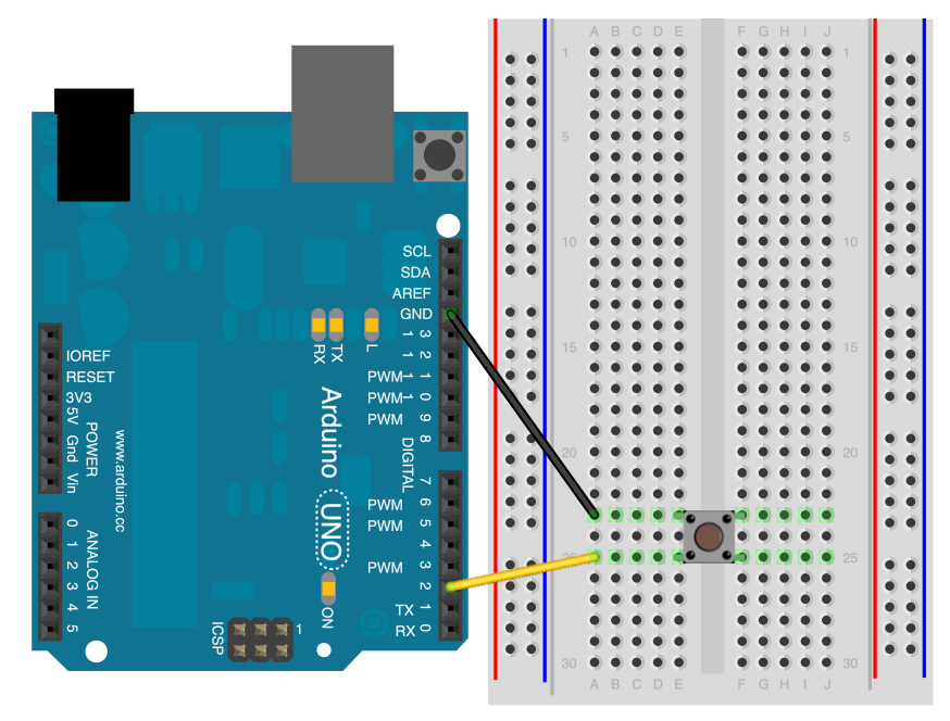
The circuit:
* Momentary switch attached from pin 2 to ground
* Built-in LED on pin 13
Unlike pinMode(INPUT), there is no pull-down resistor necessary. An internal
20K-ohm resistor is pulled to 5V. This configuration causes the input to
read HIGH when the switch is open, and LOW when it is closed.
*/
Input Pullup Serial
This example demonstrates the use of pinMode(INPUT_PULLUP). It reads a
digital input on pin 2 and prints the results to the serial monitor.
The circuit:
* Momentary switch attached from pin 2 to ground
* Built-in LED on pin 13
Unlike pinMode(INPUT), there is no pull-down resistor necessary. An internal
20K-ohm resistor is pulled to 5V. This configuration causes the input to
read HIGH when the switch is open, and LOW when it is closed.
*/
void setup(){
//start serial connection
Serial.begin(9600);
//configure pin2 as an input and enable the internal pull-up resistor
pinMode(2, INPUT_PULLUP);
pinMode(13, OUTPUT);
}
void loop(){
//read the pushbutton value into a variable
int sensorVal = digitalRead(2);
//print out the value of the pushbutton
Serial.println(sensorVal);
// Keep in mind the pullup means the pushbutton's
// logic is inverted. It goes HIGH when it's open,
// and LOW when it's pressed. Turn on pin 13 when the
// button's pressed, and off when it's not:
if (sensorVal == HIGH) {
digitalWrite(13, LOW);
}
else {
digitalWrite(13, HIGH);
}
}
Download this sketch :


0 Commentaires